
TEC Hot-Side Engineering
How to Design the Hot Side of a Thermoelectric Cooling System
A thermoelectric cooler does not make heat disappear. It moves heat from the cold side to the hot side, where the heat-rejection system must also absorb the TEC electrical input. Many systems blamed on an undersized Peltier module actually have a hot side that is too warm because the heat sink, fan, air path, interface or enclosure was evaluated under ideal rather than real equipment conditions.
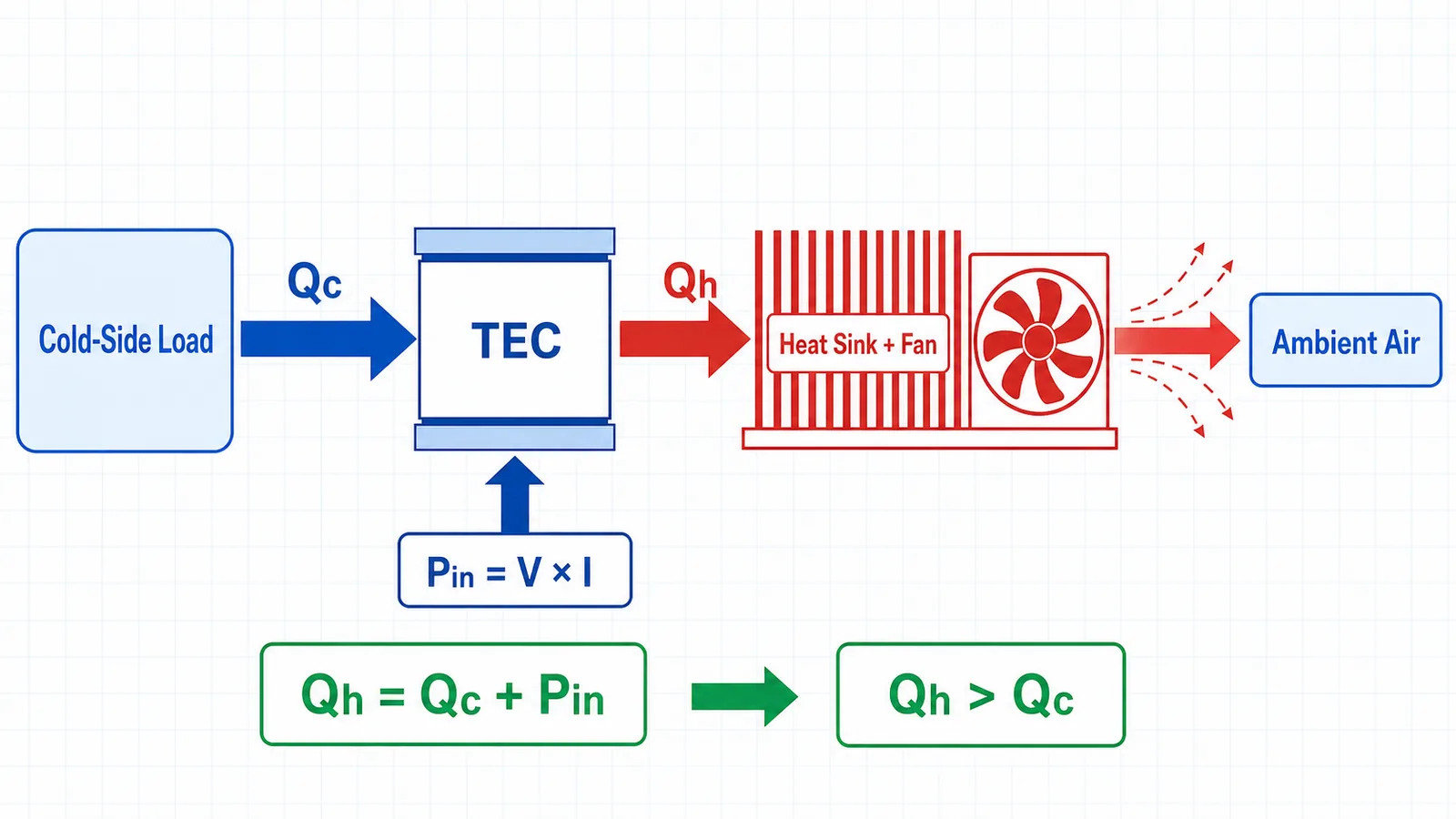
A TEC moves Qc from the cold side and adds its electrical input Pin, so the hot-side heat-rejection path must handle Qh = Qc + Pin.
1. Why the Hot Side Determines TEC Cooling Performance
A TEC creates a temperature difference between its ceramic faces while pumping heat from the cold face to the hot face. The useful cold-side capacity depends on both face temperatures, not only the model number or supplied current. If the hot side rises, the module must operate across a larger actual temperature difference to maintain the same cold-side target. That larger temperature lift normally reduces available Qc and coefficient of performance. A controller may respond to the warmer cold side by increasing current, but more current also increases electrical input and often raises Qh. Once the heat-rejection path is the limiting element, adding current can produce more hot-side heat without delivering the expected extra cooling. TEC selection and thermoelectric cooler heat dissipation therefore form one calculation loop: estimate the cold load, choose an operating point, calculate Pin and Qh, predict Th from the hot-side path, then return to the TEC data at that revised Th. Final performance must be confirmed with the selected TEC and complete equipment under representative worst-case conditions.
2. Understanding Qc, Pin and Qh
A clear energy balance prevents the most common sizing error. Qc is the heat absorbed at the cold side from the product, process, plate, fluid or air that is being cooled. It is not the TEC electrical input. Pin is the electrical power delivered to the TEC at the intended operating voltage and current. Qh is the total heat that arrives at the hot side. Use actual operating voltage and current for Pin = V × I. A supply rating, TEC maximum current or nominal module wattage does not automatically describe the selected operating point. The hot-side exchanger must reject both the transported load and the input power, so it must be selected for Qh rather than Qc alone.
Engineering relationship
Pin = V × I and Qh = Qc + Pin| Parameter | Engineering meaning | How to determine it | Common mistake |
|---|---|---|---|
| Qc | Heat absorbed at the cold-side boundary | Load calculation or measurement at the required temperature and duty | Treating TEC input watts or Qcmax as actual Qc |
| Pin | Electrical input to the TEC at the operating point | Actual TEC voltage multiplied by actual current | Using power-supply rating or module maximum values |
| Qh | Total heat delivered to the hot-side path | Qc + Pin at the same operating point | Sizing the heat sink for Qc only |
3. Calculate the Real Hot-Side Heat Load
Begin with the real cold-side thermal boundary. Include steady equipment losses, passive heat leak, product or fluid load, and any transient pull-down demand that occurs during the defined cycle. Separate continuous and short-duration loads because they may lead to different control and thermal-mass decisions. Next, obtain the TEC voltage and current from performance data at the planned Qc, cold-face temperature Tc and hot-face temperature Th. Do not substitute Qcmax, ΔTmax, Imax or the power-supply nameplate. Qcmax is generally associated with a small temperature difference, while ΔTmax is generally associated with almost no useful cold-side load; the two maxima are not a loaded equipment point. For multiple TECs sharing one exchanger, add the Qh of every operating module and account separately for nearby driver, fan, pump or enclosure losses that heat the inlet air or coolant. Recalculate whenever current, module count, ambient condition or duty cycle changes.
4. Determine the Required Heat Sink Thermal Resistance
A first-pass heat-sink target relates the allowed hot-side temperature rise to the total hot-side load. Th,max is the design limit for the TEC hot ceramic at the chosen operating point. Tamb,max must represent the hottest air entering the heat sink, not automatically the room rating. In an enclosure, inlet air may already be heated by electronics or recirculated exhaust. The resulting Rθhs is a selection boundary, not a performance guarantee. Clarify whether a supplier thermal-resistance value covers only sink-to-air behavior or includes base, interface and spreading effects. The real path can include TEC ceramic, TIM, mounting plate, heat-sink base, fins, air or liquid and the route that finally carries heat outside the equipment.
Engineering relationship
Rθhs = (Th,max − Tamb,max) / Qh- Rθhs: allowable heat-sink-to-ambient thermal resistance for the stated boundary, in °C/W.
- Th,max: maximum hot-side temperature allowed by the selected operating-point design.
- Tamb,max: maximum heat-sink inlet air or coolant reference temperature.
- Qh: total heat that the hot side must reject at the same operating point.
- Also evaluate TIM and contact resistance, base spreading, fan operating point, duct resistance, hot-air recirculation, dust and filters, orientation, altitude, internal heat sources, aging and production tolerances.
5. Simplified Engineering Example
Assume the required steady cold-side load is Qc = 150 W. Performance data for the selected TEC arrangement at the intended Tc, Th and current indicates an electrical input Pin = 120 W. The hot side must therefore reject approximately Qh = 270 W before considering other enclosure heat sources. If the maximum air entering the heat sink is 35°C and the design allows the TEC hot side to reach no more than 55°C, the available rise is 20 K. The first-pass heat-sink-to-air target is 20 K / 270 W, or about 0.074°C/W. This is demanding and may require a large forced-air exchanger, a different operating point, more space, a remote heat path or liquid heat rejection. The calculation does not prove that a catalog heat sink marked 0.074°C/W will hold the TEC ceramic at 55°C. Interface resistance, spreading, actual fan pressure, grille and filter losses, exhaust recirculation and measurement location all consume part of the temperature budget. Iterate the TEC and exchanger together, then instrument the final assembly.
Engineering relationship
Qh = 150 W + 120 W = 270 W Rθhs ≈ (55°C − 35°C) / 270 W = 0.074°C/WSimplified example
Simplified engineering example only. Final performance must be verified using the selected TEC data and the complete equipment under representative worst-case conditions.
6. Heat Sink Size, Base Spreading and Fin Design
Overall heat-sink envelope matters, but volume alone does not define performance. Heat first enters a limited contact area beneath the TEC. A base that is too thin or poorly conductive can create a local hot spot before the energy reaches the outer fins. A thicker or higher-conductivity spreader may improve uniformity, but it adds mass, cost and sometimes interface layers. Fin direction must follow the intended airflow or natural-convection direction. Spacing that looks dense can restrict a low-pressure fan, while spacing that is too wide wastes surface area. Fin height, thickness, length and bypass clearance belong to one pressure-drop and heat-transfer problem; there is no fixed geometry that suits every Qh, fan or enclosure. For multiple TECs, check heat-flux density, spacing and base temperature across every module. A heat sink with adequate average resistance can still overheat an edge or central TEC if spreading is uneven. Confirm contact areas, local Th sensors and mechanical load distribution in the production layout.
7. Fan Selection and Real Airflow
A fan free-air rating is measured near zero system resistance. Once the fan is installed behind a grille, filter, heat sink, bend or narrow exhaust, flow decreases. The real operating airflow is the intersection between the fan pressure-flow curve and the resistance curve of the assembled air path. Select for static pressure as well as flow. Measure or model the pressure drop of the heat sink, screens, filters and ducts, then consider tolerance, voltage, temperature, altitude and dust loading. Two fans can be used in series for pressure or in parallel for flow, but uneven paths, recirculation and failure behavior must be evaluated rather than inferred from simple nameplate addition. Noise limits may force lower speed or larger fans. Where thermal failure has consequences, monitor tachometer, current or airflow and define the reaction to a stalled, disconnected or degraded fan. Fan redundancy only helps if the remaining air path can support a safe derated state.
8. Prevent Hot-Air Recirculation
The effective ambient for a TEC heat sink is its inlet air. If hot exhaust returns to that inlet, Tamb rises and the available Th temperature budget shrinks even when the room remains unchanged. Compact OEM enclosures are especially sensitive because openings, cables, walls and adjacent fans can create short circulation loops. Separate intake and exhaust with distance, barriers, ducts or sealed plenums. Prevent bypass air from traveling around rather than through the fins. Check neighboring power-supply and electronics fans because they can oppose the TEC fan or feed it heated air. Multiple-fan layouts also need balanced pressure and a defined path when one fan stops. Smoke visualization, temperature probes at the inlet and outlet, and measurements with the final covers installed often reveal issues that an open-bench test misses. Evaluate every approved equipment orientation and the clearance specified for installation.
9. Air-Cooled vs Liquid-Cooled Hot-Side Heat Rejection
Hot-side heat rejection describes how Qh leaves the TEC. It is separate from the cold-side cooling medium. A system may cool circulating liquid on the cold side while still rejecting Qh through an air-cooled heat sink and fan. Conversely, a direct-contact cold plate can use a liquid-cooled hot-side exchanger. Do not interpret “liquid cooling module” without defining both sides. Air and liquid heat rejection each have valid use cases. Selection depends on heat density, available volume, remote radiator location, noise, service, orientation, leak consequence and the customer’s existing utilities. Neither method is automatically superior or maintenance-free.
| Factor | Air-cooled hot side | Liquid-cooled hot side |
|---|---|---|
| Heat-rejection capability | Depends on fin area, inlet temperature and installed airflow | Can transport dense heat to a remote exchanger; depends on flow and coolant temperatures |
| Volume and routing | Heat sink and air clearance near the TEC | Cold block near TEC plus tubing, pump and remote radiator or facility loop |
| Noise | Primarily fan and air turbulence | Pump plus radiator fan or facility equipment |
| Failure items | Fan, filter blockage and recirculation | Pump, flow restriction, air bubbles, leaks and remote exchanger |
| Maintenance | Clean fins, filters and fans | Inspect coolant, pump, seals, hoses and exchanger |
| Integration | Simpler when ambient air and space are adequate | More plumbing, sealing, fill and service requirements |
| Typical fit | Compact to moderate loads with a clear air path | High heat density, remote rejection or constrained local airflow |
10. Thermal Interface and Mechanical Mounting
The thermal path can be limited by the joint between the TEC and heat sink. Surfaces should be flat and clean enough for the chosen assembly. TIM fills microscopic voids; excessive thickness adds thermal resistance, while insufficient coverage leaves air gaps. Material selection must consider temperature range, pump-out, electrical requirements and production repeatability. TEC ceramics are strong in compression but vulnerable to bending, edge loading and impact. Apply uniform pressure through a sufficiently stiff plate or controlled clamping pattern. Tightening one corner fully before the others, using uneven screw locations or allowing tubing to pull on a plate can create poor contact and mechanical damage. There is no responsible universal screw torque for every TEC stack. Fastener size, thread, plate stiffness, spring elements, TIM, ceramic dimensions and supplier guidance determine the process. Validate pressure distribution, thermal cycling, relaxation and repeatability across production tolerances.
11. High Ambient Temperature and Enclosure Effects
An open laboratory bench can provide cool unrestricted air that never exists in the product. Inside a closed instrument, power electronics, motor drivers, lasers and supplies can raise the local inlet temperature. Covers can restrict exhaust, and a wall or cabinet can reduce external clearance after installation. Use the highest expected inlet condition, including hot climates, solar or process exposure where applicable. Air density falls with altitude, which changes fan and convective performance. Dust and loaded filters raise pressure drop, while mounting direction affects natural-convection assistance, heat pipes and air pockets in liquid loops. Test clean and aged conditions that represent the maintenance plan. Temperature sensors should distinguish room ambient, heat-sink inlet, outlet, base and TEC hot ceramic so an unexpected rise can be located rather than hidden inside one “ambient” value.
12. Sensors, Protection and Fault Handling
Normal cold-side temperature control and hot-side protection are different functions. A cold sensor reports whether the product is meeting its target. A hot-side sensor protects the TEC and assembly when airflow, coolant flow, mounting contact or ambient conditions are no longer adequate. Monitor Th near the relevant interface and supervise fan tachometer or airflow where appropriate. Liquid-cooled systems may require pump status, flow, coolant temperature, pressure or leak detection. Define thresholds from selected component data and the tested assembly, not from a universal temperature rule. Fault logic can reduce current, hold a safe derated state or shut down. It must also handle open, shorted or implausible sensors. Consider stored heat and continued conduction during shutdown: cutting the TEC and fan at exactly the same instant is not automatically safe. Evaluate post-run airflow or coolant circulation, restart interlocks, alarms and host communication for the real risk.
13. Common TEC Heat Dissipation Mistakes
Most hot-side failures are not caused by one exotic material property. They come from a boundary condition that was omitted, a catalog figure used outside its test condition or an assembly change that was not revalidated.
| Mistake | Possible effect |
|---|---|
| Sizing the exchanger for Qc instead of Qh | Th rises because TEC electrical input was omitted |
| Using fan free-air flow as installed flow | Insufficient heat transfer after real pressure losses |
| Ignoring hot-air recirculation | Heat-sink inlet temperature climbs inside the enclosure |
| Validating only on an open bench | Covers, clearances, orientation and nearby heat sources cause field shortfall |
| Ignoring TIM and contact resistance | Local hot spots and a larger ceramic-to-sink temperature drop |
| Operating continuously at maximum current | Higher Pin and Qh may reduce rather than improve useful cooling |
| Ignoring maximum ambient, altitude, dust or filters | Reduced airflow and thermal margin at real worst case |
| No independent hot-side sensor | Cold control can request more power during a hot-side fault |
| Stopping TEC and fan together without residual-heat analysis | Post-shutdown temperature excursion or unsafe restart |
| Confusing cold-side liquid cooling with liquid hot-side rejection | Wrong exchanger, plumbing and performance assumptions |
14. OEM Project Information Checklist
A useful OEM review begins with measurable boundary conditions. Share drawings and operating states rather than only a desired TEC wattage. The information below allows the module operating point, interfaces, exchanger, controls and fault responses to be evaluated together.
| Information | What to provide |
|---|---|
| Cooling target | Object, air or fluid being cooled and the controlled measurement location |
| Heat load | Steady, transient, startup and peak values with calculation or test basis |
| Temperatures | Target, tolerance, pull-down time, maximum ambient and inlet conditions |
| Mechanical envelope | Available space, enclosure drawing, contact area and mounting orientation |
| TEC electrical limits | Available voltage, current, operating cycle and existing power/control hardware |
| Air path | Inlet and exhaust direction, duct geometry, grille/filter, pressure and airflow limits |
| Acoustics and environment | Noise limit, altitude, dust, filter service interval, humidity and vibration |
| Protection and communications | Sensors, fan/pump/flow signals, alarms, derating, shutdown and host interface |
| Production plan | Prototype timing, required verification, expected annual quantity and acceptance criteria |
15. Conclusion
TEC hot-side cooling must be designed for Qh = Qc + Pin at the real operating point. The allowable thermal resistance comes from the selected Th limit and the worst inlet condition, but the final result also depends on interfaces, spreading, installed fan or coolant flow, recirculation, enclosure heat, environment, controls and fault handling. Treat the TEC, heat sink, fan or liquid loop, ducting, sensors, driver and mechanical stack as one OEM thermal system. Validate steady operation, transients, maximum ambient, installation orientation, dust or filter conditions and credible faults in the finished equipment. Arkmex can evaluate the TEC operating point and develop a complete Peltier cooling assembly around the customer’s thermal and mechanical interfaces.
Knowledge Center
Continue Reading
Explore more TEC cooling design articles from Arkmex Thermal.