Cooling
Workpiece cooling
Cool compatible workpieces within the approved surface-temperature and heat-load limits. Assess hot workpieces before placing them on the platform.

75–600 W surface temperature control with cooling, heating and temperature-holding modes
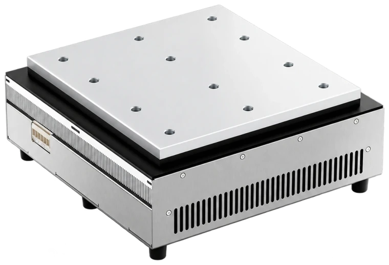
Cooling · Heating · Temperature holding
TCP platforms combine TEC contact cooling, heating and temperature holding. Sensor feedback regulates the output. Select the workpiece interface, permitted surface temperature and load for the intended conditioning, preheating or inspection cycle.
After setting the parameters, select cooling, heating or temperature holding according to operating conditions. For temperature-sensitive processes, even a fluctuation of about 1°C can affect subsequent machining or batch consistency; assess this against the workpiece and process requirements.
Workpiece cooling
Cool compatible workpieces within the approved surface-temperature and heat-load limits. Assess hot workpieces before placing them on the platform.
Controlled preheating
Confirm allowable surface and workpiece temperatures before a heating cycle. Switching to cooling follows the confirmed process conditions.
Precision machining · Inspection · Storage
Once the setpoint is reached, cooling and heating outputs are adjusted to maintain workpiece temperature, reduce the effects of excessive cooling or unstable temperature on the accuracy of the next operation, and improve temperature consistency between batches.
Relative to ambient temperature, the surface can be approximately 25°C cooler or 50°C warmer. These are reference temperature differences from the original documentation, not an absolute temperature range or guaranteed values under all conditions; actual performance must be confirmed against heat load, environment and configuration.
Select a TCP model by heat load and power supply, checking cooling capacity and power consumption separately.
| Model | Maximum cooling capacity | Maximum power consumption | Rated Voltage | Startup current | Steady-state current | Selection Support |
|---|---|---|---|---|---|---|
| TCP-75W-12V | 75 W | 102 W | 12 V DC | 8.5 A | 7 A | Enquire |
| TCP-106W-24V | 106 W | 144 W | 24 V DC | 6 A | 4.8 A | Enquire |
| TCP-150W-24V | 150 W | 204 W | 24 V DC | 6 A | 4.8 A | Enquire |
| TCP-212W-48V | 212 W | 288 W | 48 V DC | 6 A | 4.8 A | Enquire |
| TCP-300W-48V | 300 W | 408 W | 48 V DC | 8.5 A | 7 A | Enquire |
| TCP-424W-48V | 424 W | 576 W | 48 V DC | 12 A | 9.6 A | Enquire |
| TCP-600W-48V | 600 W | 816 W | 48 V DC | 17 A | 14 A | Enquire |
On mobile, swipe horizontally inside the table to view the remaining specifications.Cooling capacity and power consumption are maximum values; startup and steady-state currents are listed separately. Actual surface temperature, cooling capability and control performance depend on heat load, ambient temperature, contact thermal resistance and system configuration, and must be confirmed against the operating conditions during selection. The ±0.1°C figure is a catalogue control reference; accuracy, stability and uniformity require confirmation with the actual sensor, measuring point, load and ambient conditions. IP65 applies to the confirmed assembly; protect live terminals and assess the final equipment separately.
The seven TCP models are matched by maximum cooling capacity. Dimensions are in mm and for reference; check actual product dimensions before installation.
Maximum cooling capacity: 75 W
Overall dimensions (length × width × height)150 × 103 × 90.5 mm
Maximum cooling capacity: 106 W
Overall dimensions (length × width × height)200 × 153 × 111.5 mm
Maximum cooling capacity: 150 W
Overall dimensions (length × width × height)215 × 103 × 90.5 mm
Maximum cooling capacity: 212 W
Overall dimensions (length × width × height)300 × 153 × 104.5 mm
Maximum cooling capacity: 300 W
Overall dimensions (length × width × height)400 × 153 × 104.5 mm
Maximum cooling capacity: 424 W
Overall dimensions (length × width × height)300 × 303 × 124.5 mm
Maximum cooling capacity: 600 W
Overall dimensions (length × width × height)400 × 303 × 124.5 mm
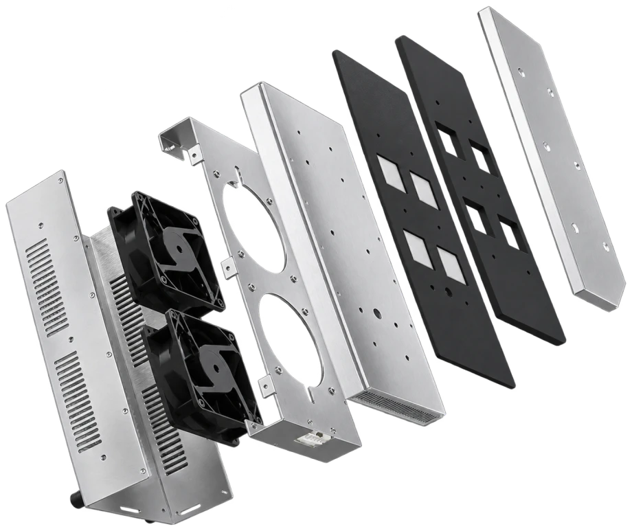
The equipment is preassembled. Check that the supply matches the selected model and connect the wiring correctly before use. The structures of the surface plate, housing, thermoelectric elements and heat sink are shown below.
Automatically determines the operating mode from measured temperature and setpoint, without manual switching.
PID control uses sensor feedback; achieved performance depends on the sensor, measuring point, load and validated settings.
Helps reduce condensation caused by temperature differences when operation pauses.
Abnormal temperature automatically cuts off the output and triggers an alarm.
Acquires temperature data and allows one computer to monitor and coordinate multiple devices.
The controller can be set from −40–+120°C; the platform operating range is −20–70°C. Check these two specifications separately.
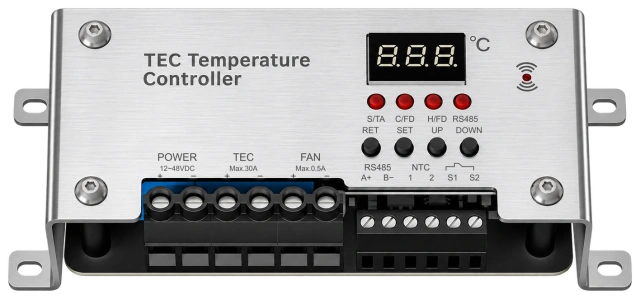
Indicator markingsS/TA · C/FD · H/FD · RS485
Button markingsRET · SET · UP · DOWN
| Panel marking | Terminals and markings | Interface description |
|---|---|---|
| POWER | 12~48 V DC;+ / − | Controller power input |
| TEC | Max.30A;+ / − | TEC output terminals |
| FAN | Max.0.5A;+ / − | Fan output terminals |
| RS485 | A+ / B− | RS485 communication interface |
| NTC | 1 / 2 | Temperature probe interface |
| S1 / S2 | S1 / S2 | Use according to the matching controller wiring instructions |
The controller's 12–48 V DC input range and the platform's rated voltage are different specifications. The matching power supply must meet the selected model's 12 V, 24 V or 48 V requirement. TEC and FAN current markings identify the respective controller terminals; they are not the complete equipment's power consumption or current. Confirm indicator meanings and the specific S1/S2 wiring against the matching controller instructions.
Concealed terminals connect the TEC, heat-rejection fan and NTC temperature-sensing signals in sequence. The following markings identify the platform interfaces.
| Marking | Interface description |
|---|---|
| T+ | Positive Peltier (TEC) power terminal |
| T− | Negative Peltier (TEC) power terminal |
| F+ | Positive fan power terminal |
| F− | Negative fan power terminal |
| N1、N2 | NTC thermistor signal output terminals connected to the controller for cooling-plate temperature sensing; B value 3950 K, resistance 10 kΩ. |
In the original 24 V example, T+ and F+ connect to positive, T− and F− to 0 V, and N1/N2 to the controller's temperature-sensing interface. With the matching controller, connect the TEC and fan to their respective output terminals.
24 V is an example only. The actual supply must match the selected model's 12 V, 24 V or 48 V rating. Maintain correct fan polarity and do not connect temperature-sensing terminals to the power supply.
Apply thermal grease between the cold-side plate and the object being cooled, then clamp evenly. Keep the contact surfaces flat and free of foreign material to reduce contact thermal resistance.
Maintain hot-side heat rejection and disconnect power if the standard air-cooling fan fails. Flow-loss protection applies only where a liquid-cooled version has been separately specified.
Supply voltage and polarity must match the nameplate. Reversing TEC current switches between cooling and heating; with a temperature controller, switching is performed by the controller. Maintain correct fan polarity.
Condensation forms when the cold surface is below the ambient dew point. Provide condensation control and drainage to prevent water from entering electrical parts.
Avoid scratching or applying concentrated loads to the temperature-controlled surface. Preserve its flatness to maintain uniform temperature.
Clean the standard air-side fan and heat sink regularly. Coolant maintenance applies only to a separately confirmed liquid-cooled configuration.
Disconnect power for prolonged storage, keep the equipment dry and avoid corrosive atmospheres.
Provide target temperature, ambient temperature, workpiece heat load and available supply to check the configuration.
Contact Form
Leave your email and any project details you already have. Our team will review the information and reply with suitable TEC / Peltier cooling options.
Name, email and phone / WhatsApp are required. Other fields are optional.
Your information will only be used for project evaluation and business communication.