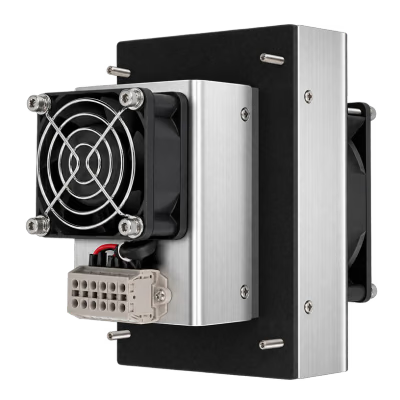
75W-12V
- Maximum cooling capacity
- 75 W
- Rated Voltage
- 12 V DC

Find a module by product family, cooling capacity and DC supply.
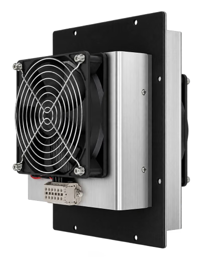
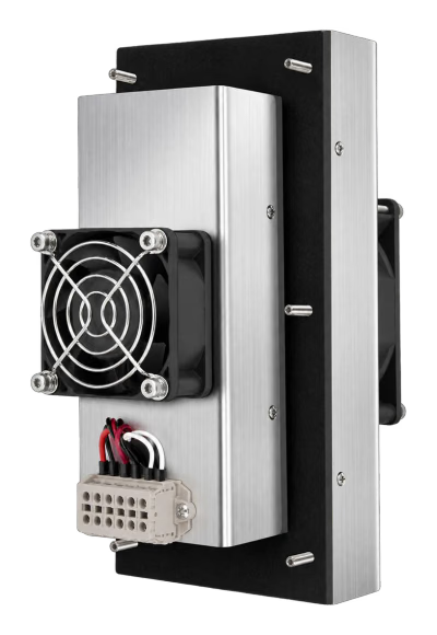
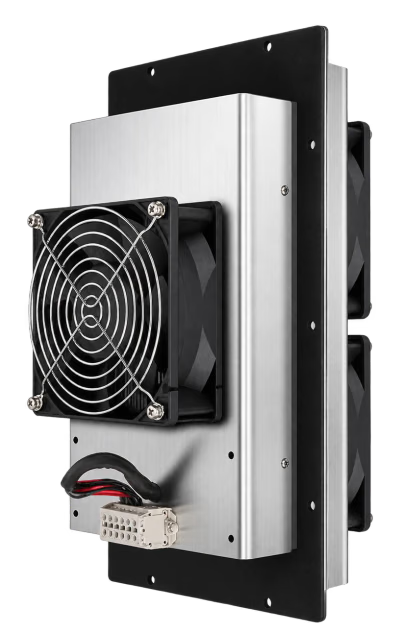
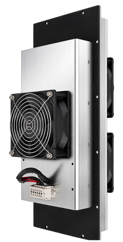
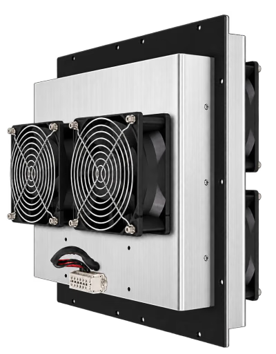
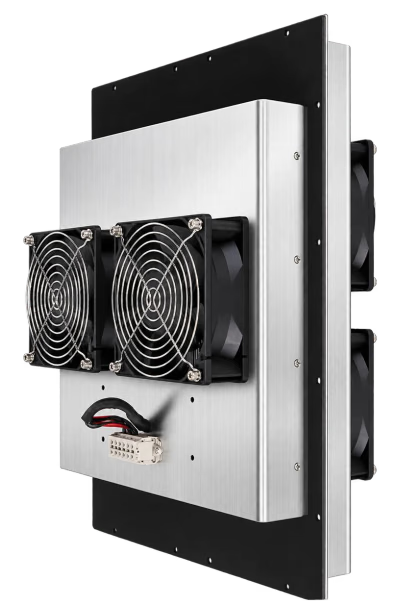
No models match these filters.
Cooling capacity and power consumption are separate quantities; both are maximum values stated in the datasheet. The datasheet does not specify the temperature difference or ambient conditions used to measure maximum cooling capacity. Model selection must therefore consider the heat load, ambient temperature, target temperature and installation conditions.
Share your heat load, target temperature and installation space.
Air-to-air thermoelectric cooling: 7 models for different installation spaces and DC supplies.
A compact solid-state air-to-air thermal management module for OEM equipment requiring localized cooling or enclosed-space temperature control. Separate hot-side and cold-side air circuits transfer heat without mixing the air on either side. The compressor-free, refrigerant-free design supports clean, low-noise integration with straightforward maintenance. Typical applications include medical and aesthetic equipment, laboratory instruments, analytical equipment, industrial control cabinets and other compact electronic systems. Mounting interfaces, airflow direction, DC voltage, fan configuration and control strategy can be adapted to project requirements.
For example, a 100 W air cooling module can cool an enclosed cabinet with a nominal internal volume of 15 L from 30 °C to 6 °C within 20 minutes at an ambient temperature of 30 °C, under no-load reference conditions.
Actual cooling performance varies with enclosure volume, insulation, construction, heat load, mounting method and operating conditions. Final cooling capacity and configuration must be evaluated for the actual application.
Selection notesCooling capacity and power consumption are separate quantities; both are maximum values stated in the datasheet. The datasheet does not specify the temperature difference or ambient conditions used to measure maximum cooling capacity. Model selection must therefore consider the heat load, ambient temperature, target temperature and installation conditions.
Provide your equipment heat load, ambient temperature, target temperature, available installation space and supply voltage so the model and mounting method can be checked.
View application example: cabinet coolingEstimated cooling after the assumed temperature correction
The product datasheet does not specify the test conditions for its maximum cooling capacities. Module selection assumes the catalogue values can be used as the reference for this correction curve; that assumption needs verification. Our engineers must confirm performance at your actual operating conditions.
Six-face wall heat transfer, solar gain on the larger vertical face plus the top, ventilation sensible heat and internal equipment heat are added, then multiplied by the safety factor. Negative ambient-to-target temperature differences are set to zero for wall and ventilation loads. The total is divided by the capacity retention to obtain the equivalent reference capacity. Curve points are joined by straight lines.
Preliminary steady-state estimate. Humidity, condensation, door openings, cool-down time and actual electrical consumption are not calculated. Material U-values, solar gains and heat ratios are fixed estimates; enclosure construction, shading and equipment losses may differ.
Open Calculator and Sizing Guide
All models: air-to-air cooling, −20 °C to +70 °C operating temperature, IP65 and optional temperature controller. On mobile, scroll the table horizontally.
| Model | Maximum cooling capacity | Maximum power consumption | Rated voltage | Current: startup / steady | Weight | Noise | Overall dimensions / mm |
|---|---|---|---|---|---|---|---|
| 75W-12V | 75 W | 102 W | 12 V DC | 8.5 / 7 A | 1.48 kg | 39 dB(A) | 103 × 150 × 153 |
| 106W-24V | 106 W | 144 W | 24 V DC | 6 / 4.8 A | 3.68 kg | 43 dB(A) | 230 × 180 × 154 |
| 150W-24V | 150 W | 204 W | 24 V DC | 8.5 / 7 A | 2.18 kg | 39 dB(A) | 215 × 103 × 153 |
| 212W-48V | 212 W | 288 W | 48 V DC | 6 / 4.8 A | 6.18 kg | 50 dB(A) | 330 × 180 × 181 |
| 300W-48V | 300 W | 408 W | 48 V DC | 8.5 / 7 A | 7.66 kg | 50 dB(A) | 430 × 180 × 181 |
| 424W-48V | 424 W | 576 W | 48 V DC | 12 / 9.6 A | 11.69 kg | 53 dB(A) | 330 × 330 × 181 |
| 600W-48V | 600 W | 816 W | 48 V DC | 17 / 14 A | 14.48 kg | 53 dB(A) | 430 × 330 × 181 |
Dimensions are in mm. Measurements were taken manually and may vary; refer to the actual product and approved drawings. Overall dimensions are listed as the illustrated panel width × height × total depth.
Expand a model to view its full specifications, overall dimensions and mounting cutout drawing. Click a drawing to open it on this page, with zoom in, zoom out and reset controls.
Product specification (English PDF)
Dimensions are in mm. Measurements were taken manually and may vary; refer to the actual product and approved drawings. Overall dimensions are listed as the illustrated panel width × height × total depth.
Ask about 75W-12VProduct specification (English PDF)
Dimensions are in mm. Measurements were taken manually and may vary; refer to the actual product and approved drawings. Overall dimensions are listed as the illustrated panel width × height × total depth.
Ask about 106W-24VProduct specification (English PDF)
Dimensions are in mm. Measurements were taken manually and may vary; refer to the actual product and approved drawings. Overall dimensions are listed as the illustrated panel width × height × total depth.
Ask about 150W-24VProduct specification (English PDF)
Dimensions are in mm. Measurements were taken manually and may vary; refer to the actual product and approved drawings. Overall dimensions are listed as the illustrated panel width × height × total depth.
Ask about 212W-48VProduct specification (English PDF)
Dimensions are in mm. Measurements were taken manually and may vary; refer to the actual product and approved drawings. Overall dimensions are listed as the illustrated panel width × height × total depth.
Ask about 300W-48VProduct specification (English PDF)
Dimensions are in mm. Measurements were taken manually and may vary; refer to the actual product and approved drawings. Overall dimensions are listed as the illustrated panel width × height × total depth.
Ask about 424W-48VProduct specification (English PDF)
Dimensions are in mm. Measurements were taken manually and may vary; refer to the actual product and approved drawings. Overall dimensions are listed as the illustrated panel width × height × total depth.
Ask about 600W-48V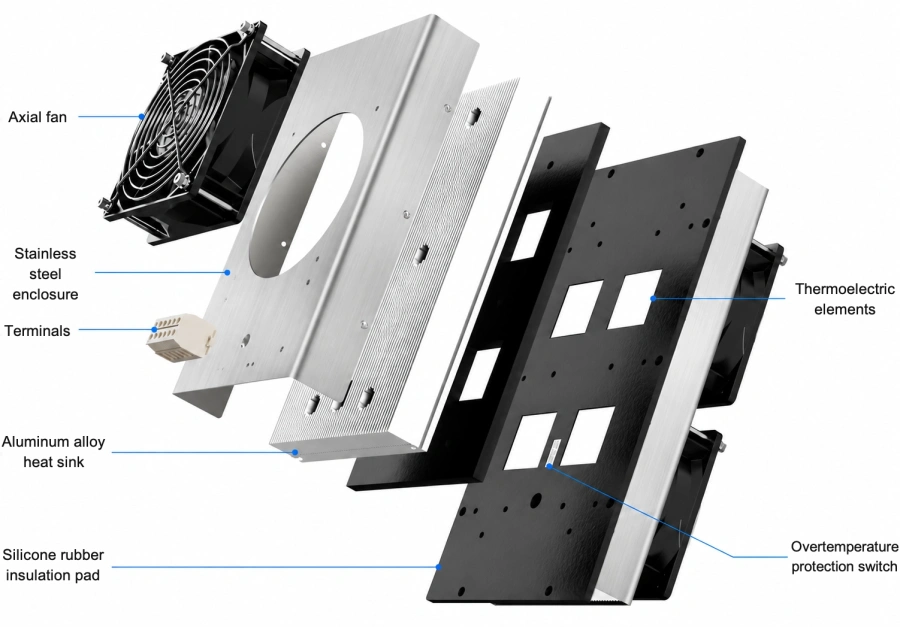
Terminal protectionThe terminals are live and must not contact liquids. The IP65 rating does not permit exposed electrical terminals to come into contact with liquids.
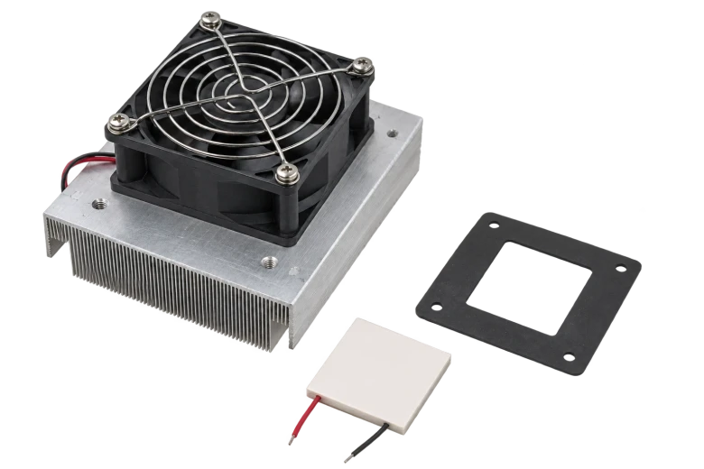
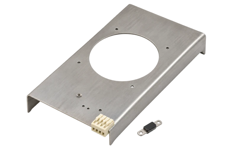
Expand the cooling principle, temperature control configuration, installation requirements and wiring instructions as needed.
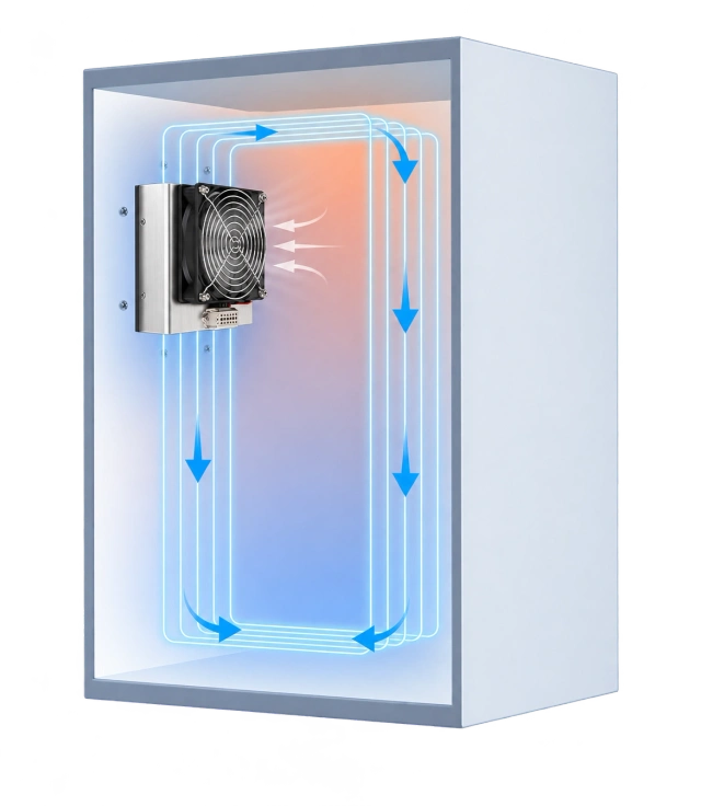
The cold-side heat sink and fan circulate cooled air inside an enclosed space. A separate external circuit, formed by the hot-side heat sink and fan, rejects heat to the ambient air. Suitable for localized or enclosed-space temperature control in cabinets, medical and aesthetic equipment, laboratory instruments, analytical equipment, industrial control cabinets and other compact electronic systems.
One side of a thermoelectric element cools while the other heats. Each side transfers cooling or heat to its surroundings through its own heat sink and fan: an internal cold-side circuit and an external hot-side circuit, with the two air paths kept separate.
The following describes different heat exchange interfaces. The models in this section are AA air-to-air modules; DA and LA distinguish other cooling solutions.
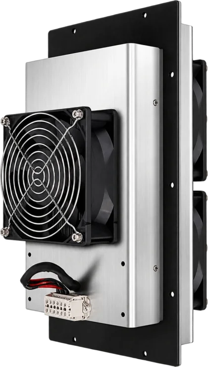
The cold-side heat sink and fan circulate cooled air within an enclosed space to reduce air temperature. All 7 products in this section use this method.
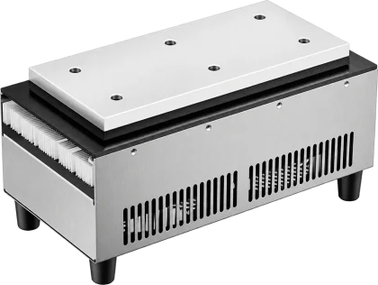
A precision-machined, highly conductive aluminum cold plate sits in close contact with the equipment, cooling it through direct conductive heat transfer.
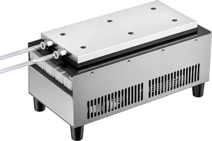
Circulating liquid flows through the cold-side heat exchanger, transferring heat through a precision-machined aluminum cold plate to cool the liquid.
An optional dedicated digital intelligent controller and DIN-rail switching power supply can form a cabinet environmental temperature control system. Selection, assembly, commissioning and online technical support are available. The controller supports automatic start/stop without continuous manual attendance.
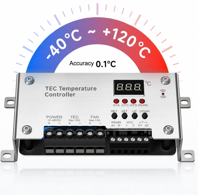
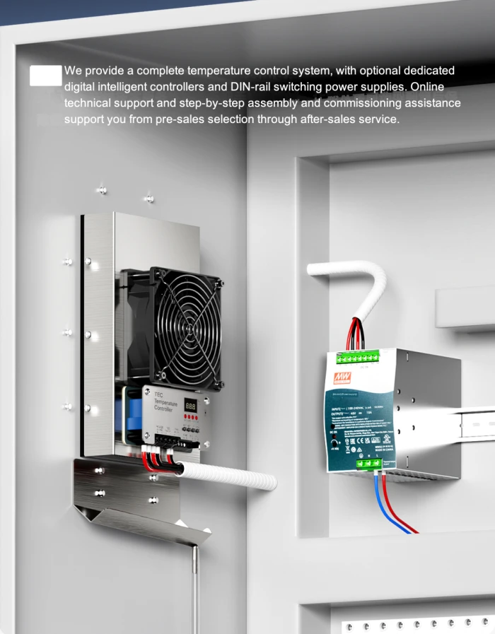
The air cooling module, digital controller and DIN-rail switching power supply can be installed together. Confirm the supporting configuration against the equipment’s supply, installation space and temperature control requirements.
Temperature specification notesThe controller’s control range and the module’s operating temperature are different specifications. The module’s operating temperature remains −20 °C to +70 °C. The controller range does not mean the module can operate throughout that range. Final temperature control accuracy must be confirmed for the complete system configuration and operating conditions.
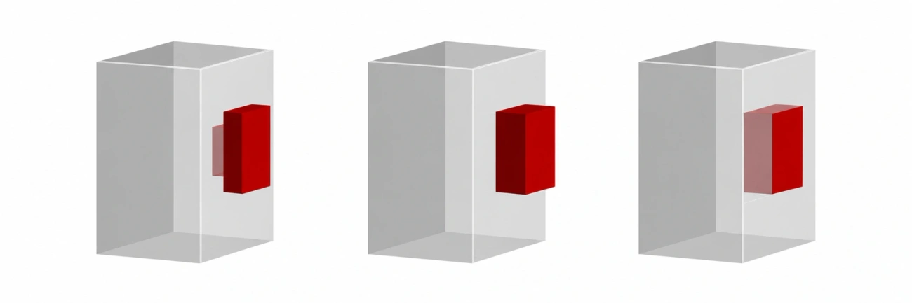
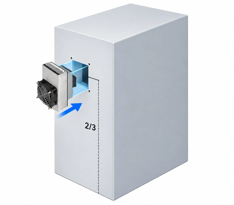
Installation at approximately 2/3 of the enclosure height above its base is recommended.
Install in the illustrated orientation and check equipment and interface positions.
Insert through a cutout sized for the cold side. See each model’s mounting cutout drawing for hole positions and dimensions.
Dimensions are in mm. Measurements were taken manually and may vary; refer to the actual product and approved drawings. Overall dimensions are listed as the illustrated panel width × height × total depth.
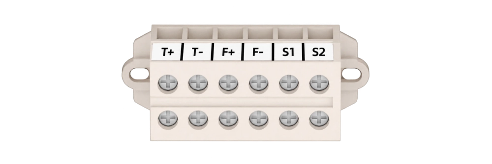
The diagram shows a 24 V DC supply as an example. The actual supply voltage must match the selected model.
Connect the thermoelectric elements, fans and overtemperature protection signal according to the terminal labels. The power supply and controller must match the model.
Terminal protectionThe terminals are live and must not contact liquids. The IP65 rating does not permit exposed electrical terminals to come into contact with liquids.
Product characteristics, appearance and construction may change as technology improves, without prior notice. Photography, layout and printing may cause slight differences between images and the actual product. The actual product and confirmed configuration take precedence.
Contact Form
Leave your email and any project details you already have. Our team will review the information and reply with suitable TEC / Peltier cooling options.
Name, email and phone / WhatsApp are required. Other fields are optional.
Your information will only be used for project evaluation and business communication.