
Applications
Thermoelectric Cooling for Laboratory Equipment
We configure TEC assemblies for local temperature control in OEM laboratory equipment. Start with the sample, reagent, detector or chamber that needs control, then define the loading cycle and the thermal interface around that task.
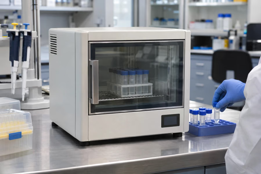
Define the sample and measurement cycle
A sample block, reagent tray and small chamber present different thermal paths. Record sample mass, container material, loading temperature and hold time. Include disturbances from opening a lid, exchanging samples or starting a process; an empty fixture test cannot represent all loaded runs.
Select the interface for the laboratory task
A contact platform can suit a compatible flat fixture. A liquid interface can serve a fluid-coupled target, while local air cooling depends on chamber mixing and leakage. Confirm the geometry and operating point before choosing TCP, a liquid module or an air-to-air assembly. LCP liquid feedback control does not establish the supply boundary of the entire circulation circuit.
Measure the functional temperature
Locate the control sensor near a representative sample or interface and compare it with a suitable reference measurement. Define accuracy, stability and spatial uniformity separately. Check the offset and settling behavior after loading, rather than treating the TEC ceramic temperature as the sample temperature.
Manage moisture and cleaning access
Cold surfaces below the local dew point need insulation and a defined condensate path. Protect connectors and nearby electronics without obstructing sample handling or cleaning. Confirm material and seal compatibility with the intended fluids and cleaning method; the cooling assembly alone does not establish cleanliness or sterility compliance.
Fit the assembly into the instrument
Allow space for mounting, thermal contact, hoses, cables and service access. Prevent tubing or fixture forces from loading the TEC unevenly. Assess fan or pump vibration and noise in the measurement setup. Confirm which controller, sensors, circulation parts and power supply are included in the selected configuration.
Validate representative laboratory runs
Test unloaded and loaded fixtures, warm sample insertion, extended holds and the specified ambient conditions. Record sensor locations, heat-load assumptions and acceptance criteria. Include relevant sensor, fan or pump faults in the equipment-level plan. Send the fixture drawing and operating cycle with the inquiry so we can assess integration and validation requirements.
For contact-surface and liquid temperature control, review Liquid Cooling Modules and Precision Temperature Control Platform. Define sensor placement and the required stability before confirming the configuration.
Related engineering resources
FAQ
Should the control sensor measure the TEC ceramic?
The process-control measurement should represent the sample or functional interface. A TEC-side sensor can serve a different protection or diagnostic role. Define both purposes and verify their temperature offset in the loaded instrument.
Does closed-loop liquid control include the whole liquid circuit?
Confirm the agreed configuration. Liquid-temperature feedback does not automatically include a pump, tank, tubing, fittings and power supply. State the circulation and supply boundaries before comparing complete solutions.
Send Your Cooling Requirement
Leave your email and any project details you already have. Our team will review the information and reply with suitable TEC / Peltier cooling options.
Applications
Continue Reading
Explore more TEC cooling design articles from Arkmex Thermal.
How Thermoelectric Cooling Modules Are Applied in Medical Laser Systems
Learn how TEC cooling assemblies stabilize laser temperature, protect optics and manage heat in compact medical and aesthetic laser systems.
Next articleThermoelectric Cooling for Analytical Instruments
Select TEC assemblies for analytical detectors, optics and sensor modules. Review drift, measurement location, heat rejection and integration limits.